Thursday, 27 February 2020

Aruba UXI Packet Capture Issue

One of the key features I hoped to make use of in the Aruba UXI sensor (formerly Cape Networks) is remote packet capture. This is performed on the sensor status page as shown below:

The problem is that it doesn't produce a file that is readable in Wireshark, with most of the 802.11 frames marked as malformed.
After raising this issue with Aruba support they came back with a response after over two weeks to say that this is a bug:
"The sensor do not capture the full packet off the wire, the snap length is 2048 bytes at the moment including the Radiotap headers, which means that sometimes wireshark won't be able to fully parse the packets.
The backend team is still working on the this."
Considering that the last update to the UXI sensor was on Aug 2019 it is a bit concerning that they either haven't noticed this issue or that they can't fix it. I can't help getting the feeling that the development of this product is on the Aruba back burner now.

Wednesday, 26 February 2020

Aruba Airwave - Correctly Scaling Floor Plans for VisualRF

In a previous post about setting the origin correctly in an VisualRF floor plan I mentioned scaling the floor plan correctly and thought I should explain how I obtain this information. Now obviously the best practise is to take your measuring tape or laser range finder and measure the actual building (remembering to take a measurement across the longest possible distance to minimise errors), however, this is not always possible. For new builds and remote sites you can get the size information from a correctly scaled PDF file.
The following instructions are for Adobe Acrobat Reader DC but equivalent functions may be available with other tools.
  1. Open the file in Acrobat Reader DC
  2. Determine the scale of the drawing, in this case there is a information box shown in the lower right corner of the drawing stating that the scale is 1:100
  3. Select Tools - Measure
  4. Click on "Measuring Tool" in the menu bar - then right click on the image and select "Change Scale Ratio and Precision" to set the scale
  5. In the window that appears set the scale according that of the drawing, in this case 1:100 i.e. 1cm on the drawing is 1m on the ground
  6. Then click on two points diagonally opposite on the plan to measure the size
  7. This length can then be used in VisualRF to set the size of a building floor plan

Tuesday, 25 February 2020

Meru Broken Virtual Cell

In a MERU (now Fortinet) single channel architecture wireless network it is normal that each AP transmits the same BSSID across the ESSID. However, if there is some slight configuration error on some APs then a situation can occur where in the same area there could be two BSSID on the same channel. This results in a hard handover when roaming and potentially client connectivity issues. Fortinet call this "broken virtual cell".

On visiting a building reporting issues with the wireless dropping connections I noticed in WinFi that there were two instances of each of our three SSIDs on channel 36:

The issue was that some of the APs were configured to 802.11an not 802.11ac causing them to create a different virtual cell.

The Fortinet documentation on this is located here.

Thursday, 20 February 2020

RSN AKM Suites

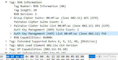
Whilst studying for CWSP I was struggling to reconcile the definition of the Authentication Key Management (AKM) Suite selector field that is contained with the RSN IE. In the CWSP-206 study guide on page 200 it is described as being either 01 (802.1X) or 02 (PSK). However, when I looked inside a packet capture in Wireshark (and also in WinFi) I could only see a decode of WPA for 802.1X networks.


Time to check the standard. On page 886 of the 80211-2016 standard there is the following table:
So the value is being correctly set in the RSN IE to 01.
For a PSK network the suite type was set to 02 and decoded as PSK which matches the standard.


So what is the take away from this, well it just appears that Wireshark is decoding the suite type of 1 correctly but giving it a confusing name of WPA to mean 802.1X.

Monday, 17 February 2020

Manual Client Blacklisting in an Aruba AOS 8 Cluster

Manually blacklisting a client in an Aruba AOS 8 cluster involves a somewhat un-obvious configuration. Normally configuration for a cluster managed by a mobility master is done at the mobility master and then pushed out to the relevant controllers based on the level of the hierarchy. In addition changes are usually  done in configuration mode on the mobility master. However, when blacklisting a client device this is done on an individual controller CLI in enable mode.

To blacklist a client, login to any controller in the cluster:

(MY-CONTROLLER-01) #stm add-blacklist-client 8CF5A3CCD483

This will push this config out to all controllers in the cluster so it doesn't appear to matter which controller this command is executed on.

This is the corresponding user trace when a client is blacklisted:
 Feb 10 12:07:01 :501103:  <3677> <WARN> |stm|  Blacklist add: 8c:f5:a3:cc:d4:83: Reason: user-defined
 Feb 10 12:07:01 :501000:  <3677> <DBUG> |stm|  Station 8c:f5:a3:cc:d4:83: Clearing state
 Feb 10 12:07:01 :522004:  <5025> <DBUG> |authmgr|  auth_cluster_ipuser_dormant_entry_delete:  ip(172.21.193.56) entry for mac 8c:f5:a3:cc:d4:83 flags 0xb
 Feb 10 12:07:01 :522004:  <5025> <DBUG> |authmgr|  AUTH GSM Macuser  Dormant Del (8c:f5:a3:cc:d4:83)
 Feb 10 12:07:01 :522004:  <5025> <DBUG> |authmgr|  ac_macuser_dormant_entry_delete: deleted dormant mac(8c:f5:a3:cc:d4:83) entry

To check which clients are currently blacklisted:

 (MY-CONTROLLER-01) #show ap blacklist-clients

 Blacklisted Clients
 -------------------
 STA                reason        block-time(sec)  remaining time(sec)
 ---                ------        ---------------  -------------------
 8c:f5:a3:cc:d4:83  user-defined  245              3355
 5c:c5:d4:de:8e:10  user-defined  2915             685
 34:02:86:b7:3d:42  user-defined  925              2675

To remove a single client from the blacklist execute the following command:
 stm remove-blacklist-client 8c:f5:a3:cc:d4:83
To remove all clients from the blacklist execute the following command:
 stm purge-blacklist-client

NB. The purge and remove commands, unlike add are not pushed out to the other controllers in the cluster so need to be run on all controllers in the cluster.

Monday, 10 February 2020

Vacation Wi-Fi Observations

Whilst on a week of skiing in Austria I couldn't help but noticing the poor state of Wi-Fi configuration is an issue over there. On arriving at the airport in Salzburg I was immediately struck by the orientation of the dipole antennas on the Cisco (3800 I think) APs. As you can see below they were tilted at 45 degrees in two directions.

Best practise is for all antennas to be in the same orientation; in this case vertically and Cisco even state this here and here
The other Wi-Fi problem I noticed was that in our hotel there was a Ubiquiti wireless network. A quick look on Wifi Analyzer showed that all the APs were configured on the same channel on both the 2.4GHz and 5GHz bands even though there were almost no neighbouring networks to interfere. At least the channel widths were sensible. Perhaps the same configuration was applied to all the APs. Surprisingly the Wi-Fi performance from a user perspective wasn't all that bad... Just goes to show that whatever poor configuration we commit sometimes Wi-Fi just works.


Emoji Wi-Fi on Cisco C9800 Catalyst

A nice feature for some situations is to use an Emoji SSID instead of a plain text SSID. Many Wi-Fi controllers support this by allowing cut...